Home
Road Map Resources
Lutherie Tools
Week 8: April 30 - May 6
 The
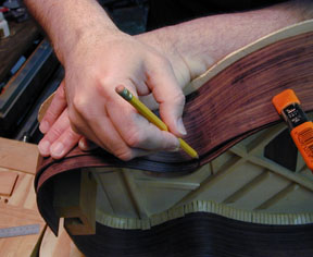
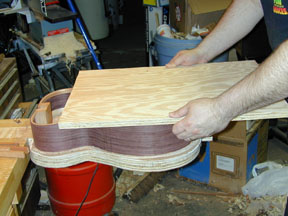
side material was about 5-1/2" wide, and the widest point of this guitar is
4". If I were smart, I thought, I would have cut it before bending. But
with my big hands, I'm sure the extra width saved me from burns on the bending
pipe. As it was, I only got two burns that developed blisters. Anyway, I cut it
down after the sides were assembled to the soundboard. I'm glad I wasn't dumb
enough to try to saw it bent but unattached. As it was, sawing it off wasn't too
big a chore. Plus, it left me this nifty inch-wide piece bent exactly to the
same form as the sides. This piece came in handy for the next operation, which
is to mark and trim the side so it slopes down. Cumpiano
and Natelson suggest using a piece of
paper for this. However, a sheet of paper would wrap around to make a continuous
slope along the side -- as if it were cut when the material was straight. What's
wanted is a slope that is straight relative to a projection of the side against
a flat surface. What you want is to see a straight line as you look from the
side of the guitar. I puzzled this out for a while, then used the off cut from
trimming the sides flat.
The
side material was about 5-1/2" wide, and the widest point of this guitar is
4". If I were smart, I thought, I would have cut it before bending. But
with my big hands, I'm sure the extra width saved me from burns on the bending
pipe. As it was, I only got two burns that developed blisters. Anyway, I cut it
down after the sides were assembled to the soundboard. I'm glad I wasn't dumb
enough to try to saw it bent but unattached. As it was, sawing it off wasn't too
big a chore. Plus, it left me this nifty inch-wide piece bent exactly to the
same form as the sides. This piece came in handy for the next operation, which
is to mark and trim the side so it slopes down. Cumpiano
and Natelson suggest using a piece of
paper for this. However, a sheet of paper would wrap around to make a continuous
slope along the side -- as if it were cut when the material was straight. What's
wanted is a slope that is straight relative to a projection of the side against
a flat surface. What you want is to see a straight line as you look from the
side of the guitar. I puzzled this out for a while, then used the off cut from
trimming the sides flat.
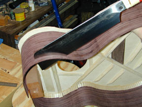 I
used the dozuki to cut a little wide
of the line, and the block plane to bring it down to the line. There's no more
room for chip out or ragged edges, as we're approaching the final outline of the
guitar. Well, alright, I still could screw up a little here and hide it under
the binding. When I think of the complexity of traditional guitar construction,
I now see the numerous opportunities to hide mistakes.
I
used the dozuki to cut a little wide
of the line, and the block plane to bring it down to the line. There's no more
room for chip out or ragged edges, as we're approaching the final outline of the
guitar. Well, alright, I still could screw up a little here and hide it under
the binding. When I think of the complexity of traditional guitar construction,
I now see the numerous opportunities to hide mistakes.
I don't have a picture of it, but this is also the way I trimmed that
inch-plus off all around. The picture would have looked pretty much just like
this one, so imagine that it serves for both.
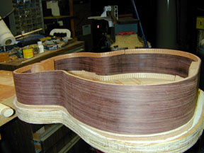
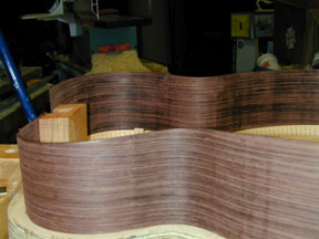 The
near side is now formed close to its final shape. The intermediate shape along
the back is parallel to the soundboard from the tailblock to a point about two
inches below the waist, then a straight slope from that point to the top of the
headblock. This is refined using a large sanding board (photo below) to
make sure that the back profile at this stage defines just these two planes. The
angle of the sloped part of the back will match the angle in the headblock that
you can see in this photo, if things work out correctly.
The
near side is now formed close to its final shape. The intermediate shape along
the back is parallel to the soundboard from the tailblock to a point about two
inches below the waist, then a straight slope from that point to the top of the
headblock. This is refined using a large sanding board (photo below) to
make sure that the back profile at this stage defines just these two planes. The
angle of the sloped part of the back will match the angle in the headblock that
you can see in this photo, if things work out correctly.
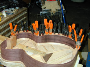 Someone
with another guitar making web site called this the obligatory photo. Actually,
it should show the kerfed lining being clamped to both sides with about a
zillion little clothespins, but I just had enough of these clamps to do one side
at a time. I didn't use the individual tentellones on the back here because,
well, it would have to be done through the soundhole! The lining is applied in
two pieces on each side, one for the level section and one for the sloped
section.
Someone
with another guitar making web site called this the obligatory photo. Actually,
it should show the kerfed lining being clamped to both sides with about a
zillion little clothespins, but I just had enough of these clamps to do one side
at a time. I didn't use the individual tentellones on the back here because,
well, it would have to be done through the soundhole! The lining is applied in
two pieces on each side, one for the level section and one for the sloped
section.
 Here's
that big sanding board, being used to level off the sides with the linings
attached, and to round over the break angle between the level and sloped parts
of the back. A slight dip at the headblock and tailblock is also imparted using
the board.
Here's
that big sanding board, being used to level off the sides with the linings
attached, and to round over the break angle between the level and sloped parts
of the back. A slight dip at the headblock and tailblock is also imparted using
the board.
As I approach the attachment of the back, it occurred to me that the six-inch
bolt I'm using to hold down the block that holds down the top will not come out
of its hole if the back is in the way! Once the back is on, I'll need to release
the box by pushing the bolt up through the workboard and fishing the block and
bolt out of the soundhole. I cut the bolt down to a more manageable length.
 Here's
the shell, ready for the back. Pretty exciting! The linings look continuous
here, but they are kerfed. The reduction of the resolution on the photo has
blurred the kerfing lines. The tiny gap you see on the far side is where the
angle breaks. It is also where one of the back braces is going to go, so the
lining will be chiseled out there anyway.
Here's
the shell, ready for the back. Pretty exciting! The linings look continuous
here, but they are kerfed. The reduction of the resolution on the photo has
blurred the kerfing lines. The tiny gap you see on the far side is where the
angle breaks. It is also where one of the back braces is going to go, so the
lining will be chiseled out there anyway.
 I've
marked and cut out the back, leaving a half-inch safety margin all around. It
will have to be trimmed right down before gluing, but the arched bracing is
going to change the dimensions slightly, so the back will be marked and trimmed
at the last step before gluing.
I've
marked and cut out the back, leaving a half-inch safety margin all around. It
will have to be trimmed right down before gluing, but the arched bracing is
going to change the dimensions slightly, so the back will be marked and trimmed
at the last step before gluing.
Cumpiano
and Natelson simply instruct you to mark the outline and cut it out at this stage.
However, you need to be aware that because the sides are sloped, the outline of
the back differs significantly, and in a complicated way, from the outline of
the top. You can't just mark it up with your template, because you will have a
big problem, even if you leave a half-inch margin. I marked the back up by
turning the box over on it and tracing around it, rocking it to make contact
with the entire edge as the pencil moved.
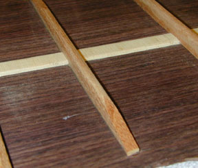
A cross-grain strip has been glued down along the center joint as reinforcement.
This could have been a cutoff from the soundboard stock, but LMI includes a
strip in its boxed materials, so I used that. I've saved the cutoff from the
back material to make the bridge patch on the next instrument.
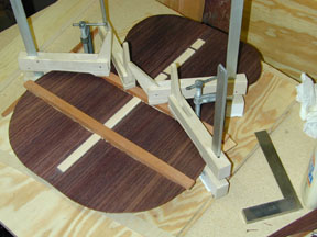
The back braces are arched more than the soundboard braces. The widest brace
here gets 1/4" off the underside of each end.
 Here
are the back braces all glued down and partly shaped. I rest the back on a plush
towel on the workbench for this work.
Here
are the back braces all glued down and partly shaped. I rest the back on a plush
towel on the workbench for this work.
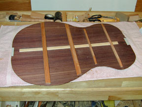
 The
back braces are shaped similarly to the soundboard braces, though they are on
the whole larger and stiffer.
The
back braces are shaped similarly to the soundboard braces, though they are on
the whole larger and stiffer.
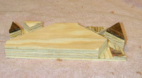 Here's
a train wreck. No, it's a bridge gluing caul. This is much more complicated than
the one in Cumpiano
and Natelson, because this smaller guitar has more braces meeting near the
bridge. This is made to go under the bridge plate to act as a caul for clamping
the bridge to the soundboard later on. The biggest part of it rests against the
bridge plate, while the small triangles fit on the other side of the x-brace,
straddling finger braces. The chuck taken out on the lower left in this photo
accommodates one of the lower face braces. Because the triangles are so small, one of them broke
off while chiseling out the gap between them. I went ahead and glued pieces of
rosewood from the cutoff from the bridge plate to see if there was any problem
fitting. Because the big part sits on the bridge plate, the small triangles
would not contact the underside of the soundboard without these pieces to act as
shims. I'm going to make a new caul along the lines of the upper face caul in
the next photo.
Here's
a train wreck. No, it's a bridge gluing caul. This is much more complicated than
the one in Cumpiano
and Natelson, because this smaller guitar has more braces meeting near the
bridge. This is made to go under the bridge plate to act as a caul for clamping
the bridge to the soundboard later on. The biggest part of it rests against the
bridge plate, while the small triangles fit on the other side of the x-brace,
straddling finger braces. The chuck taken out on the lower left in this photo
accommodates one of the lower face braces. Because the triangles are so small, one of them broke
off while chiseling out the gap between them. I went ahead and glued pieces of
rosewood from the cutoff from the bridge plate to see if there was any problem
fitting. Because the big part sits on the bridge plate, the small triangles
would not contact the underside of the soundboard without these pieces to act as
shims. I'm going to make a new caul along the lines of the upper face caul in
the next photo.
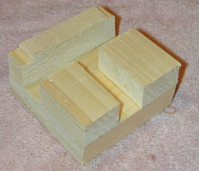 Here,
this is much nicer, isn't it? This is a caul to go under the soundboard between
the soundhole and the headblock. It will support a clamp while the fingerboard
is being glued down to the soundboard. Instead of taking a thick block of wood
or plywood and sawing and chiseling to make channels to accommodate the upper
face brace and the truss rod nut, I took a plain piece of wood and glued other
pieces to it. No train wreck. The two blocks to the lower right in this picture
sit on the upper transverse graft above the upper face brace while straddling
the truss rod nut. The block at the upper left will contact two of the soundhole
braces while the piece of soundboard cutoff glued to it contacts the soundboard
between them along the upper edge of the soundhole.
Here,
this is much nicer, isn't it? This is a caul to go under the soundboard between
the soundhole and the headblock. It will support a clamp while the fingerboard
is being glued down to the soundboard. Instead of taking a thick block of wood
or plywood and sawing and chiseling to make channels to accommodate the upper
face brace and the truss rod nut, I took a plain piece of wood and glued other
pieces to it. No train wreck. The two blocks to the lower right in this picture
sit on the upper transverse graft above the upper face brace while straddling
the truss rod nut. The block at the upper left will contact two of the soundhole
braces while the piece of soundboard cutoff glued to it contacts the soundboard
between them along the upper edge of the soundhole.
Why am I showing these cauls in the middle of fitting the back to the box?
Since they must straddle the braces to contact the soundboard snugly, they
need to be made before the back is put on, so that they can be test-fitted and
adjusted. This would be hard to do through the soundhole!
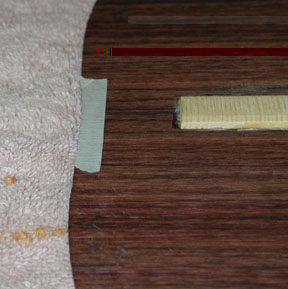 Now
that the back braces are on and shaped, the back must be fitted to the sides.
The braces are trimmed to fit exactly within the outline of the sides, and the
linings are notched out to receive the ends of the braces. To do this, the back
is places on top of the box with the braces overhanging, and the box is marked
with the locations of the brace ends, while the brace ends are marked against
the edge of the sides. The back must be exactly where it will be when attached.
It's centered along the back strip and located front to back by meeting the
bottom of the outline drawn on it earlier to the edge of the sides at the
tailblock. That line is hard to see, so I put a piece of masking tape along it.
What a pathetic excuse for including a photo, don't you think?
Now
that the back braces are on and shaped, the back must be fitted to the sides.
The braces are trimmed to fit exactly within the outline of the sides, and the
linings are notched out to receive the ends of the braces. To do this, the back
is places on top of the box with the braces overhanging, and the box is marked
with the locations of the brace ends, while the brace ends are marked against
the edge of the sides. The back must be exactly where it will be when attached.
It's centered along the back strip and located front to back by meeting the
bottom of the outline drawn on it earlier to the edge of the sides at the
tailblock. That line is hard to see, so I put a piece of masking tape along it.
What a pathetic excuse for including a photo, don't you think?
The back is held down with one hand while the marks are made with the other.
The back must be bent or rocked to make it contact both at the back and at the
front.
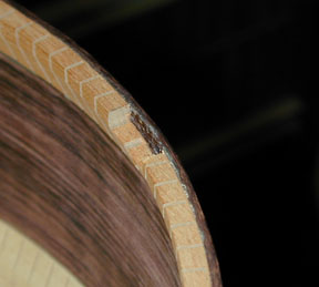 Here
is one of the notches in the lining, made by sawing with the dozuki along the
marks at a 45-degree angle and clearing the chip with a small chisel.
Here
is one of the notches in the lining, made by sawing with the dozuki along the
marks at a 45-degree angle and clearing the chip with a small chisel.
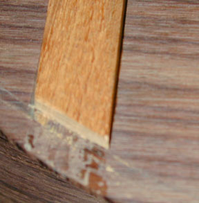 The
ends of the braces are marked along the outside of the sides, and cut off a bare
eighth of an inch inside that mark so they will (with luck) contact the side
material or come close, at the very least coming under the notch in the lining.
This adds some strength to the back in resisting stresses or blows tending to
push it in.
The
ends of the braces are marked along the outside of the sides, and cut off a bare
eighth of an inch inside that mark so they will (with luck) contact the side
material or come close, at the very least coming under the notch in the lining.
This adds some strength to the back in resisting stresses or blows tending to
push it in.
Once the braces are trimmed and fit into the notches, the back is set onto
the sides and a new outline is traces on it. The back will need to be trimmed
right down to the outline of the sides, because the method of attaching the back
can break off any overhang.
And that's as far as I got this weekend. I had hoped to get the back on this
weekend, but real life happened. The trimmed braces fit into the notched linings
quite well, and I was able to get a good tracing of the sides onto the back for
the final trimming...and then all that's left is to strap it on! Tune in next
week.
Previous Next
Home
Road Map Resources
Lutherie Tools
Copyright © 2001 Stephen Miklos